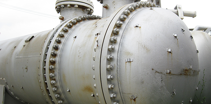
Understanding refinery fouling first requires knowing that any given type of fouling does not exist alone or as separate from other forms of fouling. Quite often, fouling will be found as a large amorphous mixture of inorganic or organic materials or polymers.
Examples of such variation is shown in the figures below:

Figure 1: samples of corrosion products constituting a mixture of inorganic materials, such as iron oxide and iron sulphide.

Figure 2: Further examples of corrosion products as present in a mixture of organic or hydrocarbon material.
These mixtures, where either not understood or verified, can often lead to incomplete or ineffective cleaning programs. For example, degreasing or decontaminating heat exchangers containing deposits comprised predominately of corrosion by-products can lead to poor outcomes such as that shown in the figure below:
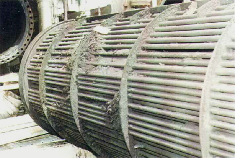
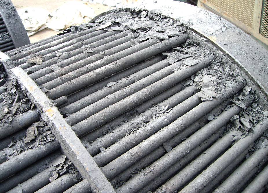
Figure 3: Corrosion deposits remaining on heat exchangers after completion of a chemical cleaning procedure. Note that many common degreasers or degasification aids are not effective for remediating these types of deposits.
Understanding both the type and degree of fouling deposition helps not only in developing a chemical cleaning program but also in estimating outcomes for assessment against stakeholder expectations. This is especially relevant where the configuration of the asset leaves areas prone to plugging or accumulation.
For example, the outcomes for a chemical cleaning program developed for a vacuum bottoms heat exchanger utilizing a vapor phase application are shown below:
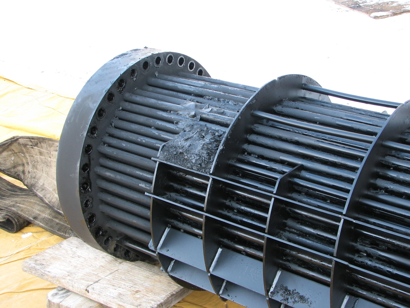
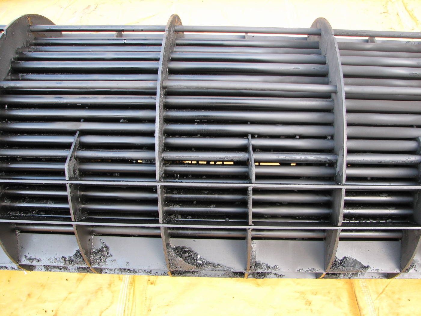
Figure 4: Opposing views of the shell side of a vacuum bottoms heat exchanger with visible coke deposits remaining on the tube bundle.
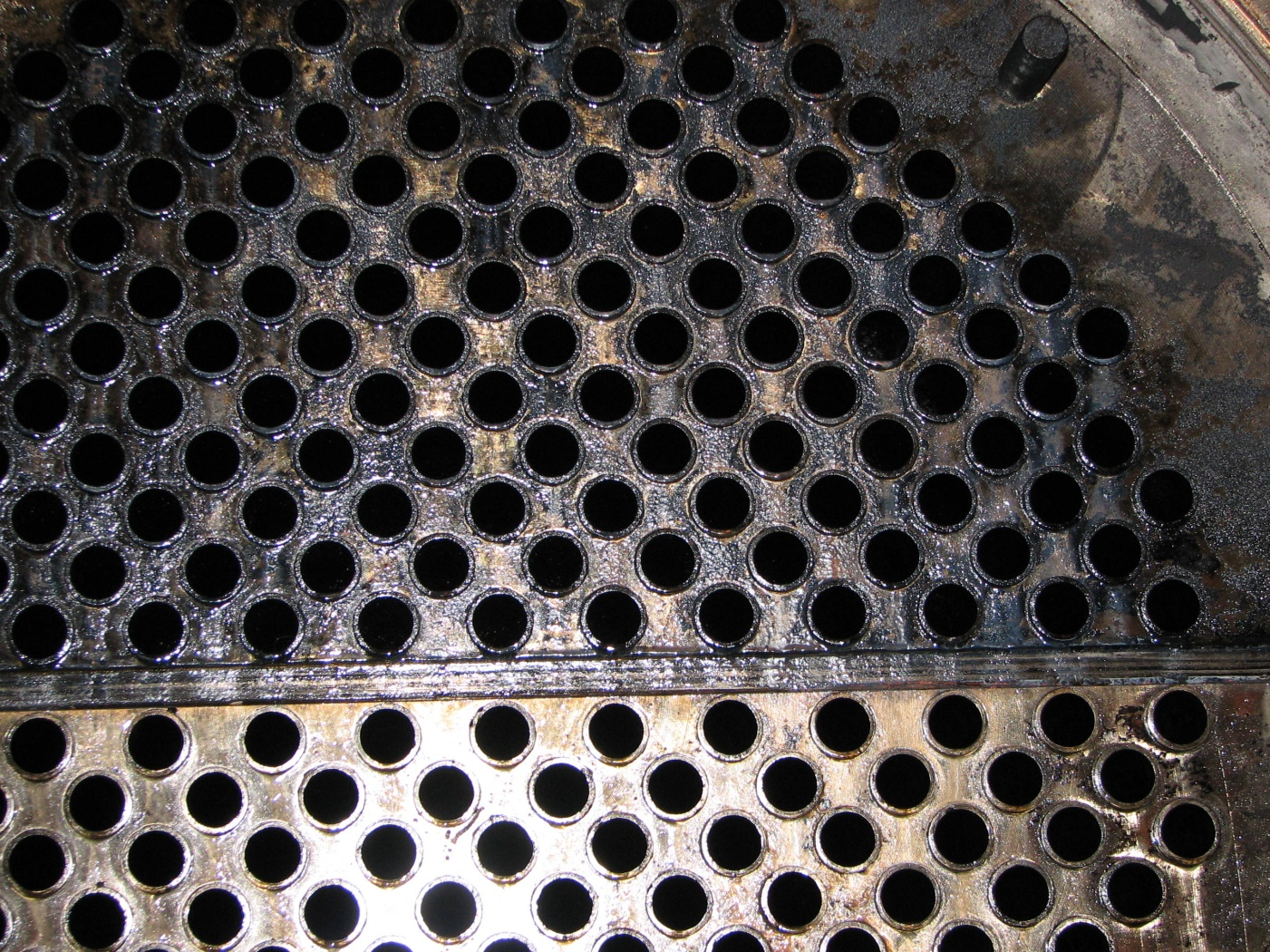
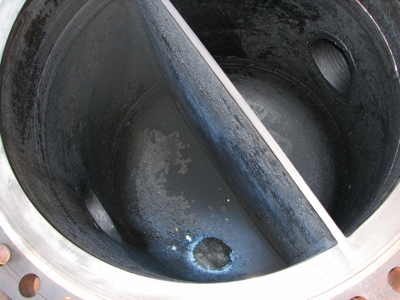
Figure 5: Tube side of the heat exchanger along with the channel head both clean and free of residual oils
Clearly, the decision to apply product by vapor phase co-injection provided optimum outcomes following known properties of the fouling and an understanding of both the asset being cleaned and the stakeholder’s expectations. This contrasts with the outcomes of a liquid circulation on a crude oil heat exchanger with many plugged tubes along with a u-type reboiler with an area of low turbulent flow on the shell side, as shown in the figures below:
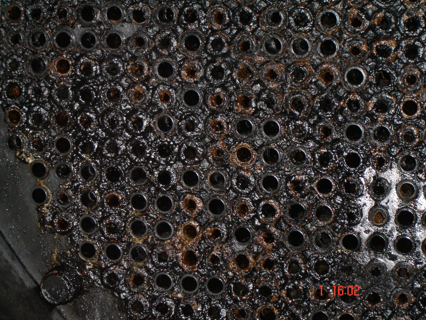
Figure 6: Plugged tubes remaining on a crude oil heat exchanger after chemical cleaning. A common issue due to a lack of liquid circulation within pre-existing plugged tubes.
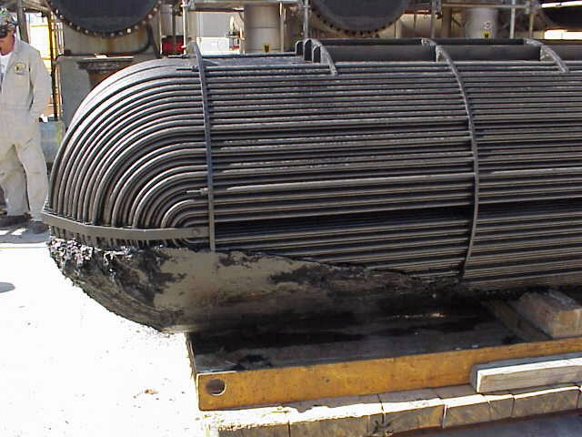
Figure 7: Large deposits on a u-type reboiler heat exchanger after chemical cleaning. A common issue in areas with a lack of turbulent flow or with deposits not readily removed by conventional decon products or procedures.
It should be noted that the outcomes for the assets shown in Figure 6 and Figure 7 were predicted. In these cases, the stakeholder was amendable to methods of mechanical cleaning and found these outcomes acceptable.
Of course, targeting certain forms of fouling with a chemical program and developing a cleaning procedure should offer outcomes that match the stakeholder’s expectations.
For example, a chemical program applied by vapor phase co-injection was utilized for an inlet receiver whose owner required it free of residual oils. This procedure did not address debris accumulation which was acceptable to the asset owner.
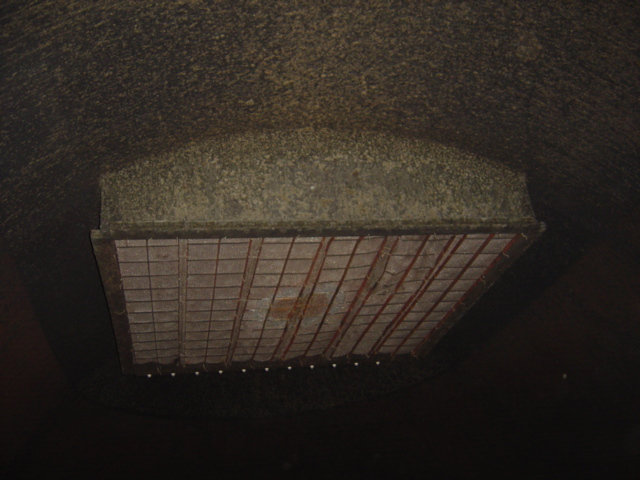
Figure 8: Top of inlet receiver vessel.
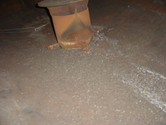
Figure 9: Bottom of inlet receiver vessel. Although large amounts of debris remain, is clean and free of residual oils as per asset owner requirements.
As the complexity, configuration, or size of the asset being cleaned changes, targeting certain forms of fouling with a particular cleaning procedure requires understanding problems that force a departure from stakeholder expectations.
For example, bridging in grid structures such as those show below can be comprised of deposits composed of coke. A form of fouling not managed by conventional chemical cleaning programs.
Problems with Bridging in Grid Structures
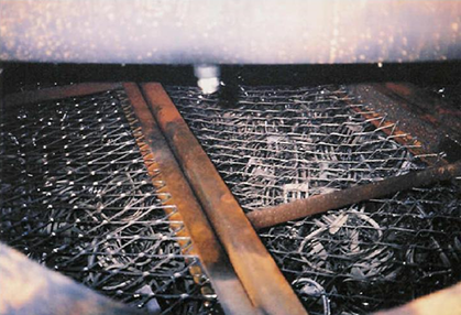
Figure 10: Packing grid of vacuum unit tower
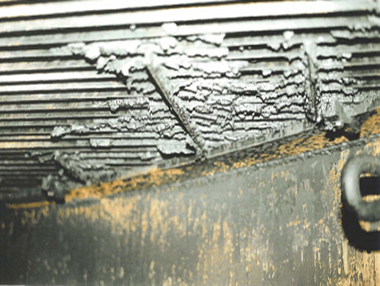
Figure 12: Underside of wash oil grid of vacuum unit tower
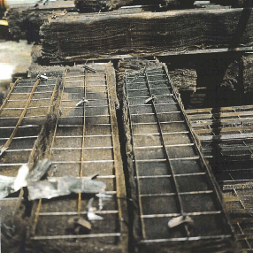
Figure 11: LVGO Demister pads of vacuum unit tower
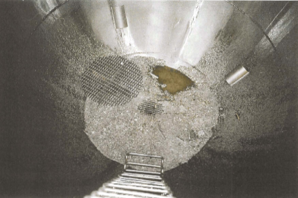
Figure 13: Bottom of vacuum unit tower
Ultimately, understanding the predominate form of fouling present helps identify the chemical to use in the cleaning procedure. In the meanwhile, outcomes of the cleaning procedure can be matched to stakeholder expectations depending on what impediments are present for efficient deposit removal.
